Gyro (IMU)
Overview
The component Gyro Accelerometer Compass provides a 9-axis Motion Processing Unit in form of a MPU9250. The component is controlled via I2C protocol.
Example
There are two example projects for the Arduino IDE which can be downloaded: MPU9250.ino (download here) and MPU-LED.ino (download here)
| ESP Board | Gyro |
|---|---|
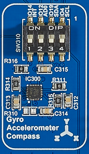 |
SW310 |
Activating the component
The component has a dip switch SW310 for activating the component.
| Function | SWITCH | IO port | Conflicts with | Remarks |
|---|---|---|---|---|
| INT | 1 | 14 | mikroBus, SW404-2, INT; Camera, SW402-4, D2; SD Card, SW406-5, CLK; Grove Digital2, SW207-1, IO14 | |
| AD0/SD0 | 2 | 12 | RFID, SW303-2, IRQ; mikroBus, SW404-1, PWM; Camera, SW402-3, D1; SD Card, SW406-2, DAT2; Grove Digital1, SW206-1, IO12 | |
| SDA/SDI | 3 | 19 | RFID, SW303-3, MISO; OLED, SW309-2, SDA; TFT, SW314-1, MISO; mikroBus, SW405-2, MISO; Unit-Bus, SW200-2, CN212 - PIN5; Grove I2C, SW203-1, I2C-SDA | I2C Pull-up by SW307 |
| SCL/SCLK | 4 | 4 | OLED, SW309-1, SCL; Camera, SW402-1, RCK/RCKL; SD Card, SW406-3, DAT1; Unit-Bus, SW200-1, CN212 - PIN 6; Grove I2C, SW203-2, I2C - SCL | I2C Pull-up by SW308 |
Using the component
Switch on I2C PULL-UP at SW307 and SW308.
First you should define two constants for the two I2C signal lines: SDA (serial data) and SCL (serial clock):
1 2 | #define SDA 19 #define SCL 4 |
Additionally constants for the addresses of the IMU component are recommended:
1 2 3 4 5 6 7 8 9 10 11 12 | #define MPU9250_ADDRESS 0x68 #define MAG_ADDRESS 0x0C #define GYRO_FULL_SCALE_250_DPS 0x00 #define GYRO_FULL_SCALE_500_DPS 0x08 #define GYRO_FULL_SCALE_1000_DPS 0x10 #define GYRO_FULL_SCALE_2000_DPS 0x18 #define ACC_FULL_SCALE_2_G 0x00 #define ACC_FULL_SCALE_4_G 0x08 #define ACC_FULL_SCALE_8_G 0x10 #define ACC_FULL_SCALE_16_G 0x18 |
With two utility functions (defined in the sample project Gyro.ino) data is read and write from the I2C bus. With these functions the component is configured in the setup method:
1 2 3 4 5 6 7 8 9 10 11 12 13 14 15 16 17 18 19 20 21 22 23 24 25 26 27 | void setup() { // Arduino initializations Wire.begin(SDA,SCL); Serial.begin(115200); // Set accelerometers low pass filter at 5Hz I2CwriteByte(MPU9250_ADDRESS,29,0x06); // Set gyroscope low pass filter at 5Hz I2CwriteByte(MPU9250_ADDRESS,26,0x06); // Configure gyroscope range I2CwriteByte(MPU9250_ADDRESS,27,GYRO_FULL_SCALE_1000_DPS); // Configure accelerometers range I2CwriteByte(MPU9250_ADDRESS,28,ACC_FULL_SCALE_4_G); // Set by pass mode for the magnetometers I2CwriteByte(MPU9250_ADDRESS,0x37,0x02); // Request continuous magnetometer measurements in 16 bits I2CwriteByte(MAG_ADDRESS,0x0A,0x16); // Store initial time ti = millis(); Serial.println("MPU9250"); } |
In the loop method you could access the three IMU components.
Accelerometer
1 2 3 | int16_t ax = -(Buf[0]<<8 | Buf[1]); int16_t ay = -(Buf[2]<<8 | Buf[3]); int16_t az = Buf[4]<<8 | Buf[5]; |
1 2 3 | int16_t gx = -(Buf[8]<<8 | Buf[9]); int16_t gy = -(Buf[10]<<8 | Buf[11]); int16_t gz = Buf[12]<<8 | Buf[13]; |
Magnetometer
1 2 3 4 5 6 7 8 9 10 11 12 13 14 15 16 17 18 | uint8_t ST1; do { I2Cread(MAG_ADDRESS,0x02,1,&ST1); } while (!(ST1&0x01)); // Read magnetometer data uint8_t Mag[7]; I2Cread(MAG_ADDRESS,0x03,7,Mag); // Create 16 bits values from 8 bits data // Magnetometer int16_t mx = -(Mag[3]<<8 | Mag[2]); int16_t my = -(Mag[1]<<8 | Mag[0]); int16_t mz = -(Mag[5]<<8 | Mag[4]); |
Sample project
There are two example projects for the Arduino IDE which can be downloaded: MPU9250.ino (download here) and MPU-LED.ino (download here).