Menu
Overview
The component MENU has five switches which could be used for control tasks.
Example
An example project for the Arduino IDE can be downloaded: Button.ino (download here)
| ESP Board | menu |
|---|---|
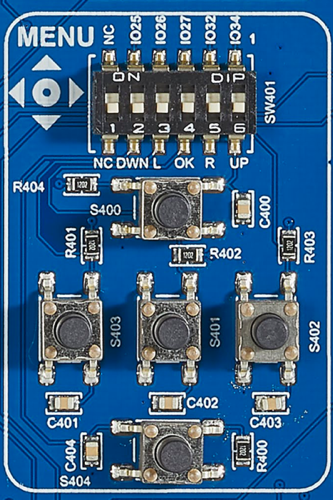 |
SW401 |
Activating the component
The component has a dip switch SW401 for activating the buttons. Each of the five buttons is connected to one IO port. Switch 1 is not connected and therefore the state of this switch is not relevant. The buttons are connected to the following ports
| Function | SWITCH | IO port | Conflicts with | Remarks |
|---|---|---|---|---|
| Button UP | 6 | 34 | CAMERA, SW400-3, D7; GROVE, UART, SW205-1, ADC6 | |
| Button DOWN | 2 | 25 | CAMERA, SW400-1, D5; Audio, SW306-3, LRCLK | |
| Button LEFT | 3 | 26 | CAMERA, SW402-6, D4; Audio, SW306-2, BCKL | |
| Button RIGHT | 5 | 32 | CAMERA, SW400-4, VSYNC; SD CARD, SW407-1, LED | |
| Button CENTER | 4 | 27 | CAMERA, SW402-5, D3; SD CARD, SW407-2, CDET |
Using the component
It's very important to switch on the right switches on SW401. Additonally it's recommend to define constants for the IO ports of the appropriate ports. This could be done as follows:
1 2 3 4 5 | #define BTN_UP 34 #define BTN_DOWN 25 #define BTN_LEFT 26 #define BTN_RIGHT 32 #define BTN_CENTER 27 |
Before you could use the buttons, you have to setup the io ports.
1 2 3 4 5 6 7 8 9 10 | void setup() { pinMode(BTN_UP,INPUT); pinMode(BTN_DOWN,INPUT); pinMode(BTN_LEFT,INPUT); pinMode(BTN_RIGHT,INPUT); pinMode(BTN_CENTER,INPUT); } |
1 | Serial.begin(115200); |
Now you could read the state from the Button. If you press the button you get a 0, otherwise you get a 1.
1 2 3 4 5 | void loop() { Serial.print(digitalRead(BTN_UP)); delay(250); } |
Sample project
An example project for the Arduino IDE can be downloaded: Button.ino (download here).