mikroBUS
Overview
The component mikroBUS™ comprises a pair of 1×8 female headers with a proprietary pin configuration and silkscreen markings. The pinout (always laid out in the same order) consists of three groups of communications pins (SPI, UART and I2C), six additional pins (PWM, Interrupt, Analog input, Reset and Chip select), and two power groups (+3.3V and 5V).
Example
An example project for the Arduino IDE is coming soon.
| ESP Board | mikro Bus |
|---|---|
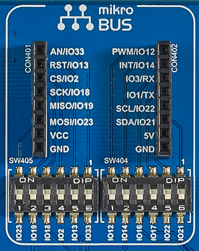 |
SW404,SW405 |
Activating the component
| Function | IO port | switch |
|---|---|---|
| PWM | IO12 | SW404-1 |
| INT | IO14 | SW404-2 |
| RX | IO16 | SW404-3 |
| TX | IO17 | SW404-4 |
| SCL | IO22 | SW404-5 |
| SDA | IO21 | SW404-6 |
| MOSI | IO23 | SW405-1 |
| MISO | IO19 | SW405-2 |
| SCK | IO18 | SW405-3 |
| CS | IO2 | SW405-4 |
| RST | IO13 | SW405-5 |
| AN | IO33 | SW405-6 |
Using the component
Sample project
An example project for the Arduino IDE is coming soon.