M5CAMERA
Description
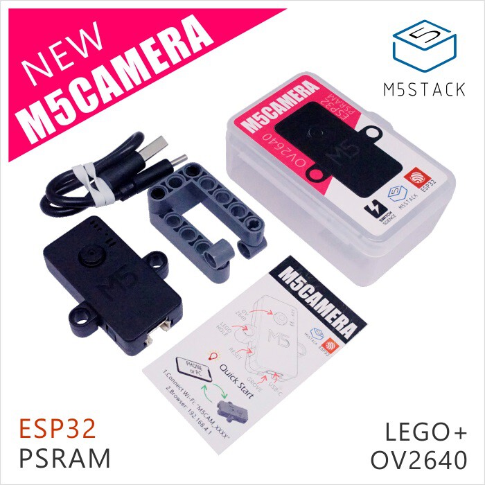
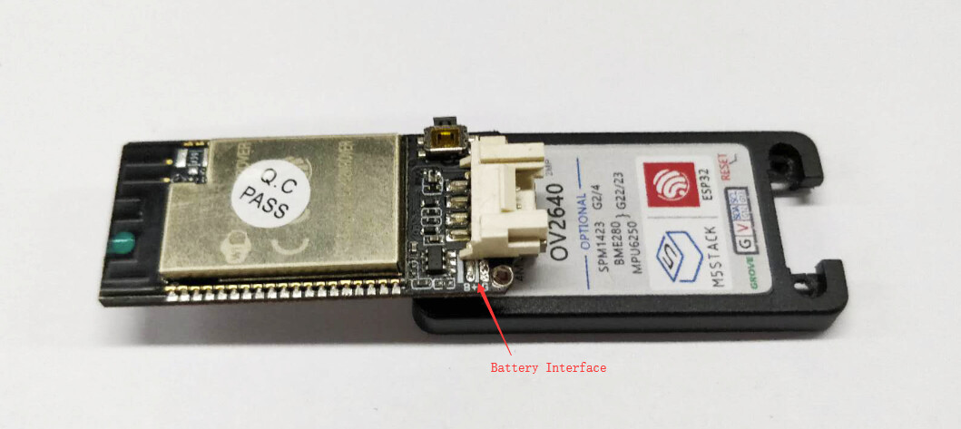
The M5Camera is a camera unit based on ESP32 chip and OV2640 including PSRAM. You can even program it through ESP-IDF or Arduino IDE.
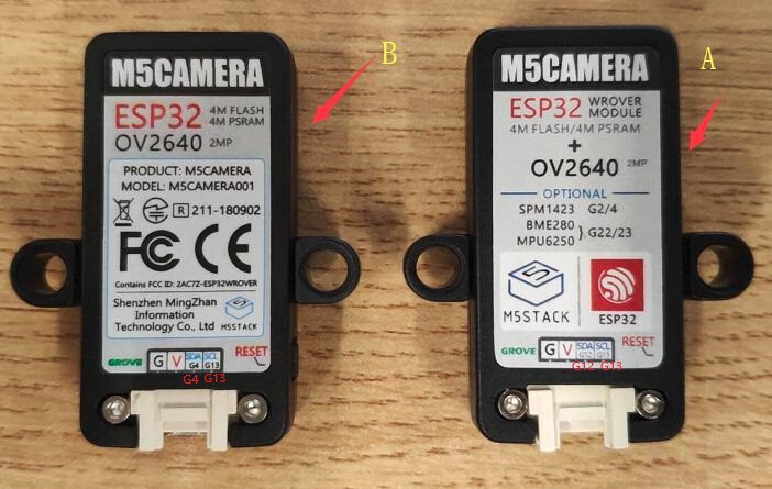
There are two versions of M5Camera Unit: A Model and B Model.
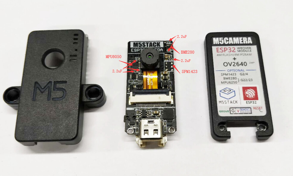
This Unit reserves the weld of the 9-axis gyroscope (MPU6050), Temperature and humidity pressure sensor (BME280) and Digital silicon microphone (SPM1423). If you need those devices, you can Self-weld them or purchase those version thraightly. Additionally, M5Camera also reserves the weld of battery.
Note: M5Camera is named differently when different hardware is selected. They follow the rules below.
M5Camera_#_#... means optional hardware name follows "M5Camera".
- If configured with MPU6050, will be named M5Camera_6050
- If also configured with microphone, will be named M5Camera_6050_MIC
- If also configured with BME280, will be named M5Camera_6050_MIC_BME280
Feature
- ESP32 specifications
- Dual-core Tensilica LX6 microprocessor
- Up to 240MHz clock frequency
- 4MB PSRAM
- 4MB Flash memory
- Integrated 802.11 BGN WiFi transceiver
- Integrated dual-mode Bluetooth (classic and BLE)
- Hardware accelerated encryption (AES, SHA2, ECC, RSA-4096)
- CP2104 USB-to-TTL converter
- OV2640 sensor
- Output Formats(8-bit):
- YUV(422/420)/YCbCr422
- RGB565/555
- 8-bit compressed data
- 8-/10-bit Raw RGB data
- Maximum Image Transfer Rate according to specific format
- UXGA/SXGA: 15fps
- SVGA: 30fps
- CIF: 60fps
- Scan Mode: Progressive
- Output Formats(8-bit):
- Camera specifications
- CCD size : ¼inch
- Field of View : 78 degree
- Maxmium Pixel: 200W
- Sensor best resolution: 1600 * 1200
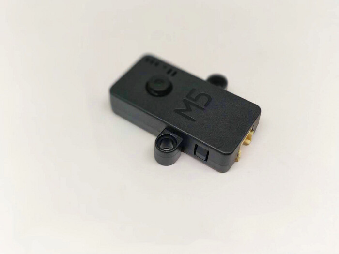
- Dimension: 40 × 49 × 13mm
Include
- 1x M5 Camera
- 1x Type-C USB Cable
PinMap
There are two versions of M5Camera Unit: A Model and B Model.
Camera Interface PinMap
| Interface | Camera Pin | M5Camera(A model) | M5Camera(B model) |
|---|---|---|---|
| SCCB Clock | SIOC | IO23 | IO23 |
| SCCB Data | SIOD | IO25 | IO22 |
| System Clock | XCLK | IO27 | IO27 |
| Vertical Sync | VSYNC | IO22 | IO25 |
| Horizontal Reference | HREF | IO26 | IO26 |
| Pixel Clock | PCLK | IO21 | IO21 |
| Pixel Data Bit 0 | D2 | IO32 | IO32 |
| Pixel Data Bit 1 | D3 | IO35 | IO35 |
| Pixel Data Bit 2 | D4 | IO34 | IO34 |
| Pixel Data Bit 3 | D5 | IO5 | IO5 |
| Pixel Data Bit 4 | D6 | IO39 | IO39 |
| Pixel Data Bit 5 | D7 | IO18 | IO18 |
| Pixel Data Bit 6 | D8 | IO36 | IO36 |
| Pixel Data Bit 7 | D9 | IO19 | IO19 |
| Camera Reset | RESET | IO15 | IO15 |
| Camera Power Down | PWDN | see Note 1 | see Note 1 |
| Power Supply 3.3V | 3V3 | 3V3 | 3V3 |
| Ground | GND | GND | GND |
GROVE Interface
| Grove | M5Camera(A model) | M5Camera(B model) |
|---|---|---|
| SCL | IO13 | IO13 |
| SDA | IO12 | IO4 |
| 5V | 5V | 5V |
| GND | GND | GND |
LED Interface
| LED | M5Camera(A model) | M5Camera(B model) |
|---|---|---|
| LED_Pin | IO14 | IO14 |
The following tables are Reserved Chip Interfaces
BME280 Interface
It's IIC address is 0x76.
| BME280 | M5Camera(A model) | M5Camera(B model) |
|---|---|---|
| SCL | IO23 | IO23 |
| SDA | IO22 | IO22 |
MPU6050 Interface
It's IIC address is 0x68.
| MPU6050 | M5Camera(A model) | M5Camera(B model) |
|---|---|---|
| SCL | IO23 | IO23 |
| SDA | IO22 | IO22 |
MIC(SPM1423) Interface
| MIC(SPM1423) | M5Camera(A model) | M5Camera(B model) |
|---|---|---|
| SCL | IO2 | IO2 |
| SDA | IO4 | IO4 |
NOTE:
-
Camera Power Down pin does not need to be connected to ESP32 GPIO. Instead it may be pulled down to ground with 10 kOhm resistor.
-
We have several kinds of camera boards, the following figures show the main differece with them. If you want to view the detailed defference with them, please click here.
If you want to download the detailed defference with them, please click here.

Related Link
Code
Firmware
Example
Schematic
Power circuit

Chip peripheral circuit

USB to serial port part of the circuit

Related Video
M5Camera Application - Image transmission between M5Camera and M5Core