OLED-LCD
Overview
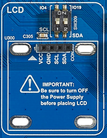
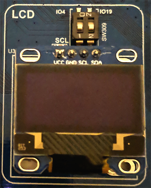
The component LCD supports monochrome OLED displays with a resolution of 128*64 pixel driven by a SSD1306 driver. The display is not soldered to the board, but there is a four pin connector for an OLED display. The right image shows the component with connected display.
Example
There are four example projects for the Arduino IDE which could be downloaded:
OLED_1.ino (download here) for demonstration
Temp-OLED.ino (download here) how to show a logo and the temperature
Flappy Bird (download here) the game and
Pong (download here) also a game.
| connector | OLED |
|---|---|
 |
 |
Activating the component
The component has a dip switch SW309, which has to be activated in order to use the component. The component is connected to the following ports:
| Function | SWITCH | IO port | Conflicts with | Remarks |
|---|---|---|---|---|
| SCL | 1 | 4 | Gyro, SW310-4, SCL/SCLK; Camera, SW402-1, RCK/RCKL; SD Card, SW200-1, CN212 - PIN 6; Grove I2C, SW203-2, I2C - SCL | I2C Pull-up by SW308 |
| SDA | 2 | 19 | RFID, SW310-3, MISO; Gyro, SW310-3, SDA/SDI; TFT, SW314-1, MSIO; mikroBus, SW405-2, MISO; Unit-Bus, SW200-2, CN212 - PIN 5; Grove I2C, SW203-1, I2C- SDA | I2C Pull-up by SW307 |
Using the component
Info
Required libraries
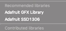
In order to use the component you need two libraries: Adafruit SSD1306 and Adafruit GFX library. The latest version of the Adafruit SSD1306 library could be downloaded from the GitHub repository. Additionally you could download a tested version. After the download it's necessary to add both libraries to your Arduino IDE. Open Sketch > Include Library > Add .ZIP Library ... and select the downloaded archive. Do it for both libraries.
After a successful installation the menu Sketch > Include Library should contain an entry Adafruit GFX library and Adafruit SSD 1306* in the category Recommended libraries.
Import the necessary libraries
Caution
It's important that you use the "-sign for including the Adafruit_SSD1306 library. With the quotation marks the enviroment searches first in the local directory for this library. Here it's important that you put a patched version of this library in your working directory of the sketch. You need Adafruit_SSD1306.h and Adafruit_SSD1306.cpp.
1 | #include "Adafruit_SSD1306.h" |
You need both libraries (Adafruit_SSD1306, Adafruit GFX) for using this sample codes. In case of compilation error you should check whether you have added both libraries to your Arduino development environment. The Adafruit GFX library is used from Adafruit_SSD1306.
Setup the display
The first step is to create an instance of the class Adafruit_SSD1306 in order to work with the display.
1 2 | #define OLED_RESET 4 Adafruit_SSD1306 display(OLED_RESET); |
Open the display on the I2C addr 0x3D (for the 128x64).
1 2 3 4 | void setup() { Serial.begin(9600); display.begin(SSD1306_SWITCHCAPVCC, 0x3C); } |
Note
The line Serial.begin(9600) is only for debugging purposes. You could remove this line if you don't need outputs in the Serial console.
Draw a Pixel
1 2 | display.clearDisplay(); display.drawPixel(10, 10, WHITE); |
Draw many lines
1 2 3 4 5 6 7 8 9 10 11 12 13 14 15 16 17 18 19 20 21 22 23 24 25 26 27 28 29 30 31 32 33 34 35 36 37 38 39 40 41 42 43 44 45 46 47 48 49 50 51 52 | void testdrawline() { for (int16_t i=0; i<display.width(); i+=4) { display.drawLine(0, 0, i, display.height()-1, WHITE); display.display(); delay(1); } for (int16_t i=0; i<display.height(); i+=4) { display.drawLine(0, 0, display.width()-1, i, WHITE); display.display(); delay(1); } delay(250); display.clearDisplay(); for (int16_t i=0; i<display.width(); i+=4) { display.drawLine(0, display.height()-1, i, 0, WHITE); display.display(); delay(1); } for (int16_t i=display.height()-1; i>=0; i-=4) { display.drawLine(0, display.height()-1, display.width()-1, i, WHITE); display.display(); delay(1); } delay(250); display.clearDisplay(); for (int16_t i=display.width()-1; i>=0; i-=4) { display.drawLine(display.width()-1, display.height()-1, i, 0, WHITE); display.display(); delay(1); } for (int16_t i=display.height()-1; i>=0; i-=4) { display.drawLine(display.width()-1, display.height()-1, 0, i, WHITE); display.display(); delay(1); } delay(250); display.clearDisplay(); for (int16_t i=0; i<display.height(); i+=4) { display.drawLine(display.width()-1, 0, 0, i, WHITE); display.display(); delay(1); } for (int16_t i=0; i<display.width(); i+=4) { display.drawLine(display.width()-1, 0, i, display.height()-1, WHITE); display.display(); delay(1); } delay(250); } |
Scroll text
1 2 3 4 5 6 7 8 9 10 11 12 13 14 15 16 17 18 19 20 21 22 23 | void testscrolltext(void) { display.setTextSize(2); display.setTextColor(WHITE); display.setCursor(10,0); display.clearDisplay(); display.println("scroll"); display.display(); delay(1); display.startscrollright(0x00, 0x0F); delay(2000); display.stopscroll(); delay(1000); display.startscrollleft(0x00, 0x0F); delay(2000); display.stopscroll(); delay(1000); display.startscrolldiagright(0x00, 0x07); delay(2000); display.startscrolldiagleft(0x00, 0x07); delay(2000); display.stopscroll(); } |
Text display tests
1 2 3 4 5 6 7 8 9 10 11 12 | display.setTextSize(1); display.setTextColor(WHITE); display.setCursor(0,0); display.println("Hello, world!"); display.setTextColor(BLACK, WHITE); // 'inverted' text display.println(3.141592); display.setTextSize(2); display.setTextColor(WHITE); display.print("0x"); display.println(0xDEADBEEF, HEX); display.display(); delay(2000); display.clearDisplay(); |
Invert the display
1 2 3 4 5 | display.invertDisplay(true); delay(1000); display.invertDisplay(false); delay(1000); display.clearDisplay(); |
Sample project
A sample project for the Arduino IDE is provided in OLED_1.ino (download here). The following image shows the OLED output of this sample project:
| OLED_1.ino | example |
|---|---|
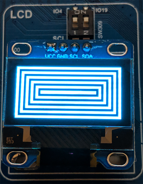 |
showing output |
Create your own picture
Here a short summary how to show your logo at the display.
Procedure with GIMP and Notepad++:
Open image with GIMP
Crop the image to the content
Scale image to 128 pixels wide (and LINEAR)
Export file as file type xbm (X-BitMap image)
Edit "xbm" file with Notepad ++
Change variable in third line to: "static unsigned char"
Save file as "images.h"
A sample project for the Arduino IDE is provided in Temp-OLED.ino (download here). The following image shows the OLED output of this sample project:
| Temp-OLED.ino | example |
|---|---|
| showing logo of MakerFactory |
Flappy Bird
An interesting project for the Arduino IDE is the game Flappy Bird (download here).
Pong
Another interesting project for the Arduino IDE is the game Pong (download here).